
3. General Advice on Modeling
basic principles and guidelines
Author: bac9-flcl
basic principles and guidelines
Author: bac9-flcl
The next thing I'd like to cover is the modeling process itself. I am going to assume you have already studied all the tutorials in the "New to Google SketchUp" tutorial section of official site. If you are not yet confident with the way how tools work, open up the Instructor window:
")
")
It is displaying the information about the currently selected tool along with an awesome animated examples, and is quite helpful.
I also recommend to keep all the modifier key combinations and hotkeys in mind, as they are greatly speeding up your workflow and are often helping you to create cleaner geometry.
3.1. Mesh structure
edges, faces, face directions
All SketchUp models are consisting of edges and faces. You should keep in mind that under the hood there is a traditional simple 3D model based on vertex coordinates, and that all your faces are in fact already triangulated, but right during the modeling process you will work only with the edges and seemingly non-triangulated faces with unconditioned side count.
Creating faces in SU is a very frequent activity, and it's very simple: all you need is a coplanar closed loop of edges, once you have it (side by side with the Line tool or straight away with something like Rectangular/Circle tools), the face is automatically created.


Hovewer, for some reason, a lot of SU modelers forget about one thing: the direction in which the created surface is facing. And there we get to the very important issue.
Quote:
sketchup makes realy bad meshes
Quote:
sketchup engine itself creates a lot of problems for any 3D software (doble-sided planes, wrong backfacing and so on)
It is a common belief that the SketchUp itself is faulty in terms of surface orientation, and no matter how you work with it, it'll always produce inverted faces and other errors. That is not true, and, as aforementioned, the modeler himself should keep an eye on that, just like in any other DCC package.
The face direction is very easy to determine, as SketchUp is using color indication to display face direction:

In this example, the white face is facing upwards, while the blue one is facing downwards. Remember: the white is a color of the front side, and all your model surface should be covered with it. There are only a few exceptions like transparent textures which will be covered separately.
To reverse the face orientation, right click on it and choose Reverse Faces context menu action. Like that:
")
Here are some examples of proper and improper geometry:
")
Remember: when creating a face in a closed edge loop, SketchUp has no idea what face direction is right for you. And you shouldn't blame it for that

")
Unless... you already have some adjacent face(s) around. In that case, SketchUp knows exactly what direction are you looking for. Here's the example:
")
")
Remember: in the most cases, the back faces won't be there in other 3d formats, so make sure they are on the inside of the surface and are not used in any way. This applies to texturing too: never use backfaces to apply textures. Here's the example on how the model will look if you'll use the back surface.
")
To sum it up:
")
Always check your model for faces with incorrect orientation. I should also mention that if your model is already textuted, you can switch to the monochrome mode where only face direction is displayed. Just choose View -> Face Style -> Monochrome, instead of Shaded With Textures. Of course, you'll need to apply the texture again in case you'll reverse certain face direction.
3.2. Mesh combination
handling of adjacent surfaces, welding
During the modeling process, we constantly encounter adjacent surfaces, contacting parts and so on, basically every structure has these. It's good to know how SketchUp handles such cases and what should be avoided.
The main difference between e.g. adjacent parts in 3ds Max and adjacent parts in SketchUp is that SketchUp geometry is always solid and welded. Here are several examples.
Let's draw two colinear surfaces with a parallel edge, then match them in SU.

You will get a single mesh which can be moved and modified as a whole. You can even erase the old edge now:

It can be called "sticky geometry". Quite self-explanatory term.
Sound useful? Yes, if is, in many cases. But not always. Let's take a look on the other example (I've triangulated all the surfaces to visually demonstrate the mesh structure changes and differences).
Let's create a cube and a vertical plane, and then superpose one of the cube's sides on that "wall".

^ here's what we'll get in 3ds Max, the mesh stayed the same, the cube and the wall are still separate objects

^ and there's what we get in SketchUp: once free parallel surfaces adjoin, the mesh is welded
If you are not sure why the welding is not good in this particular case, take a look at the following, not so abstract examples. Let's use some kind of a wall lamp instead of a cube:
")
")
Or a simple clock:

")
Or a stair (my eyes are bleeding on this one, polycount became 100 times bigger then it was).
")
")
I guess you already know how we should sum this up: NEVER DO THAT.
Ok, sure, we won't ever match the geometry that we do not want to weld. But then how are we supposed to assemble complex objects? The answer is simple: with separating the model into components.
3.3. Making of the optimized model
utilizing groups and components
The components are nice little things you'll use about a several thousand times, so I'd recommend to watch this tutorial video by Google very thoroughly. (Though, to be honest, I hope you've already watched it as was asked in the beginning of the tutorial.)
To clear this from the start: you'll never need to use Groups, there are no downsides for using instanced Components all the time. Even if some part like room is used only once in your model, make it a Component. Just because this way you can, for example, make a copy of it away from an assembled building and make all the necessary changes without obstructions from the surrounding building geometry.
Basically, every single part (that you want to be free) you use in your building should be a separate component. Some modular source objects can contain up to several thousands of them. Here's the example with the stair.
")
")
But you should use them logically, where it makes sense. It's not really needed to separate each and every part in the individual component: just make sure that every pair of contacting parts is situated in the different component. For example, look at this detailed broken wall:

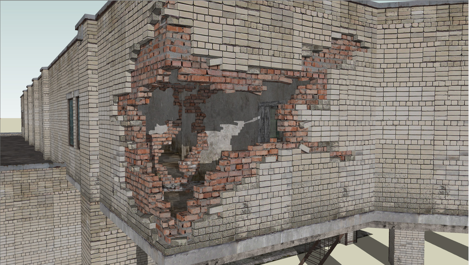
In fact, it is composed from only two components:
")
So let's examine the cases where you should and should not utilize the model separation.
For the first one, let's take a look at some indoor corridor. Should we separate a floor and a wall into the different components, or it better to use solid geometry there? It depends.
")
As you see in this example, the decision depends on whether these parts share the same amount of subdivisions and positions of vertices on the border. If they align perfectly, then you can combine the geometry without producing new edges.
Let's take a look at more complex, practical examples:
")
")
Obviously, we won't combine the walls and floor in the first example as it'll produce unwanted additional geometry, - but the second example looks normal, and welding it is a good idea (you'll get reduced vertex count at no additional cost).
By the way, all of this applies to wall/ceiling separation, but I'd recommend not to include the ceiling in the wall geometry nor to make it share the component with the floor. The reason is simple: with ceiling being
The most obvious case to discuss there is how the whole generic building should be separated. No problem.
")
Here you can download the .skp model of the building depicted above, consisting of 15 components: http://www.playuptools.com/downloads/extras/ExampleBuilding.skp
")
I hope it'll serve as a useful reference.
When the model is done and by no chance you'll need any modular flexibility to edit it again, you can simplify the component structure and hierarchy. It's not mandatory (well, it is only in case your hierarchy is too complex (e.g. 4+ levels) for some applications (e.g. PlayUp exporter) or for some other reasons), so if you aren't forced to simplify the object structure - don't do that. It's always awesome to have the possibility to, for example, extract some neatly organized window components from the building you've made a year ago and utilize them in the new model.
If you're simplifying the component structure, rules are simple:
1. Everything that's not contacting can be combined.
2. It's better to combine only closely situated (e.g. parallel window separators) or functionally similar elements (e.g. a row of columns on the facade).
3. Analyze the object and split it with functional approach even if you're not going to edit it again, - it never hurts to have a neatly organized hierarchy where e.g. windows are combined with windows and small brick parts are combined with small brick parts.
Example of finalized component structure:
")
>> PART IV: Materials & Textures <<